
Calculation Module Plates
I moved next to the structure of the calculations modules, which consists of three carbon fiber plates that fit between the previously made pillars. These are not necessarily complicated to make, but have many hole patterns that put them at risk of being rendered obsolete if a design change needs to be made in the future. Still, I was concerned about how well the workings of the module would translate from a temporary structure over so it’s a necessary risk.
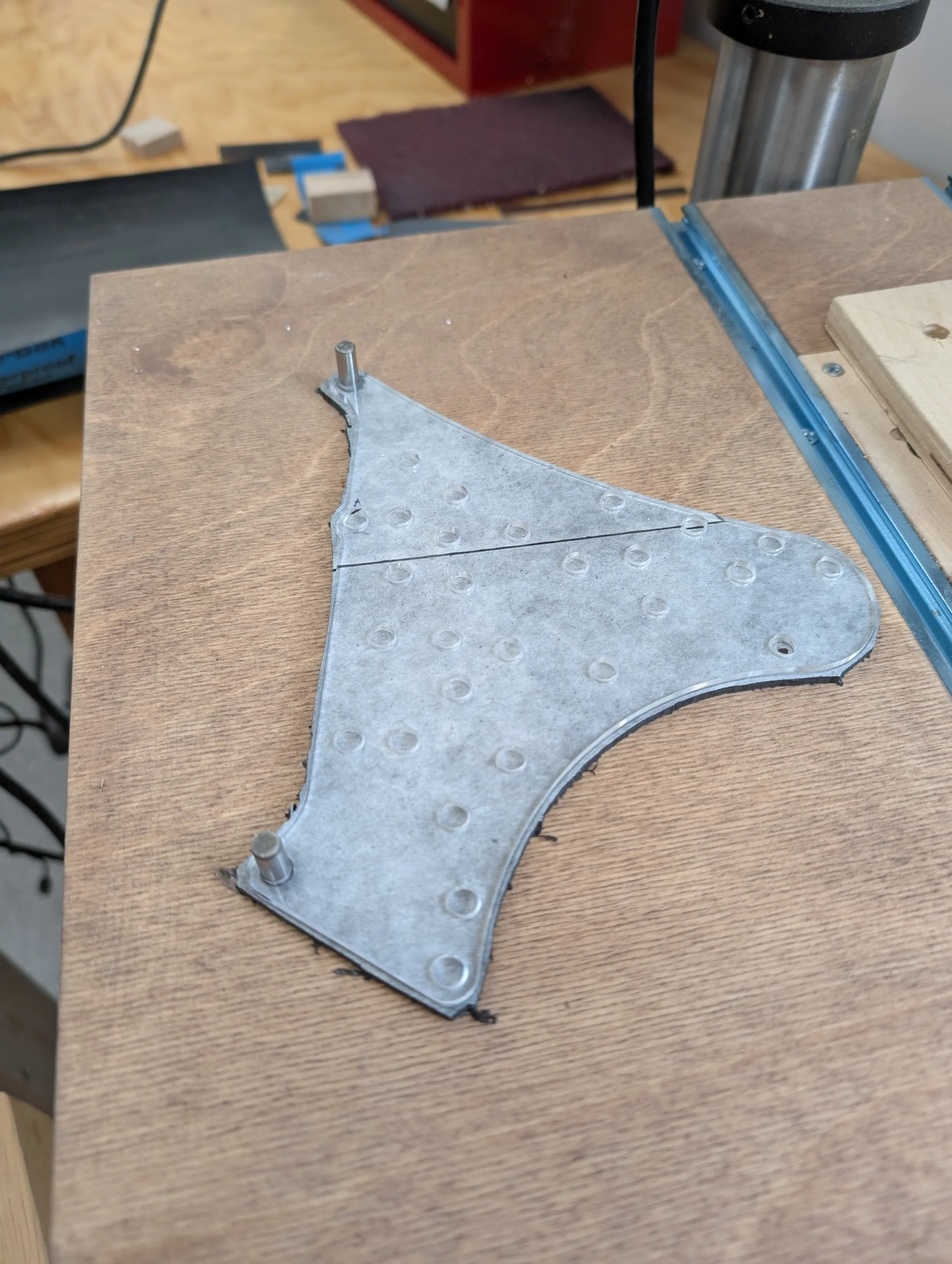
Like the larger clock plates, I use an approach of cutting an acrylic template on the laser cutter for each plate that I then use for tracing the perimeter, locating holes, and routing the perimeter to shape.

Starting with roughing out the perimeter on the portaband. The shape was traced from the acrylic template.
Drilling first the holes for the support pillars as primary datums, using the acrylic template as a drill guide. Here the two holes on the left have been drilled and have pins to maintain alignment while the third hole (on right) is drilled.

Sequentially adding the other two plates to ensure the end result has all three pillar holes match drilled together, and each plate has its three holes correctly located relative to the roughed outline

Each plate’s acrylic template is then dowel pined to the pillar holes and used as a drill template for the remaining holes. The perimeter is also routed to match the acrylic shape with a template bit

After deburring and edge sanding, the final plates assembled with the pillars
More information on NAWCC Forum post on this subject: