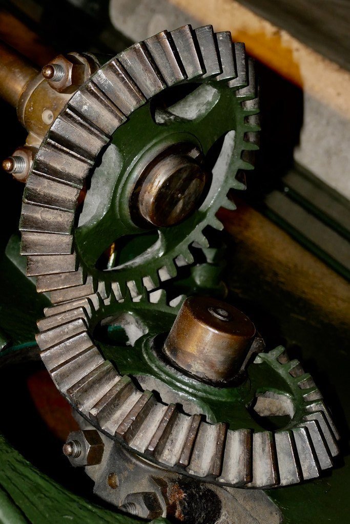
Cutting Bevel Gears
What Makes Bevel Gears Difficult?
While spur gears have no variation in shape throughout their thickness, and therefore easily cut through methods such as laser cutting, bevel gears inherently have an angled profile that necessitates a 3D manufacturing method. Furthermore, a correctly profiled bevel gear has a teeth whose profile changes across it’s length, which means that conventional gear cutting isn’t sufficient (looking at the images to the right, you can imagine if the gears were thickened they would taper to a point where their axes intercepted and thus would need infinitely small teeth). Together these make bevel gears more challenging to machine, but it is still a task well within a hole machine shop.


Calculating Bevel Gear Dimensions
The first steps in designing a bevel gear is to know what inputs to define. For a standard pressure angle, there are just 4 that affect the gear cutting:
Tooth Count: It’s quite common to have the same tooth count on both gears, if it’s being used only to reorient a drive shaft.
The Gear Module: Now recall the module varies throughout the thickness, we care about it at the front face. This will be the gear cutter size utilized, so it’s good to match an existing set if you have one.
Bevel Angle: 45 degrees is the most common, to produce a 90 deg gear set, but it could be anything from 0 (spur gear) to 90 (crown gear) degrees.
Tooth Width: The most subjective, this is largely aesthetic. Thick teeth can carry more load, but will suffer more error in the tooth profile at the rear face of the gear. A good rule of thumb is 0.2x the gear diameter.
Calculating the dimensions that result from this are fairly straightforward, I suggest just using this Excel worksheet to run all the calculations. Ivan Law’s Gear & Gear Cutting For Home Machinists is a tremendous resource if you want to learn more about this part.
Machining Bevel Gears
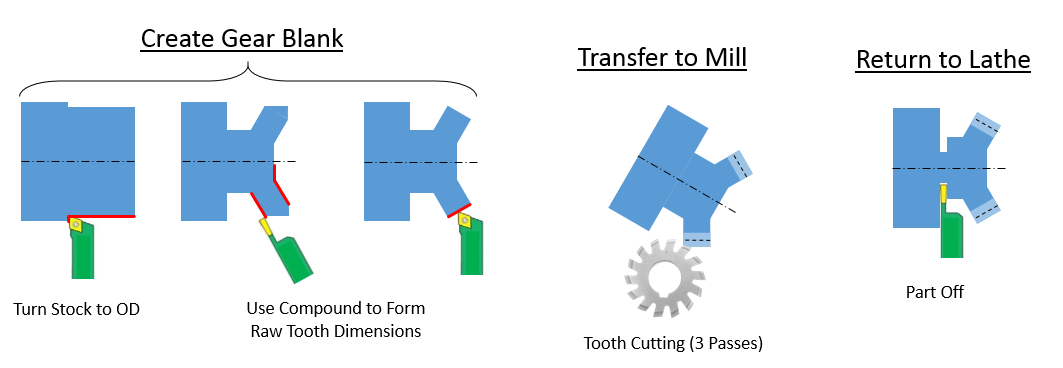
The general flow of machining bevel gears is the same as a normal spur gear with a bit more complexity in each step:
Create a gear blank on the lathe. Bevel gear will need to utilize the compound slide (or rotated headstock for Sherline-style lathes) to get the angled tooth profile
Transfer to a mill with dividing head to cut the teeth. In additional to the normal pass, bevel gears need two additional ‘flank’ passes with minor shifts in the angle and cutter height. This corrects for the non-constant tooth module.
Return to lathe to part off of the parent stock